

For boards and project directors, a bridge is among the highest-risk infrastructure assets to deliver: large contract values, tight geometric tolerances and very little room for error once a heavy element is in the air. This is where bridge construction simulation in 3D and 4D becomes a decision-making tool rather than a visual presentation. This article explains why erection sequences are hard to visualize with conventional drawings, what 3D and 4D simulation can test, how it affects risk and cost, and how a contractor or asset owner can adopt it in a realistic, staged way.
Why the Bridge Erection Sequence Is Hard to Visualize
The erection sequence is hard to visualize because a bridge is never in its final form during construction. The structure changes every day: foundations and piers come first, falsework and temporary supports are installed, girder segments are lifted one by one, and the supports are removed only once the structure can carry its own weight. Two-dimensional drawings almost always show the finished condition, while the greatest risks sit in the conditions in between.
Several factors reinforce one another. First, many disciplines work at the same time, namely civil, structural, geotechnical, heavy equipment and logistics, and each reads the drawings from its own viewpoint. Second, working space is often constrained by a river, live traffic, existing utilities or a narrow site, so the position of cranes, storage areas for segments and haul routes becomes a puzzle of its own. Third, methods such as balanced cantilever, incremental launching or the use of a launching gantry create dependencies between stages that are difficult to capture in a schedule table.
As a result, method decisions often rest on the experience of a few senior individuals and on verbal explanation. That experience is valuable, but it is hard for others to test, hard to communicate to the asset owner, and easy to lose when staff change. For management, this means high-value decisions are taken with information that is not uniform across stakeholders.
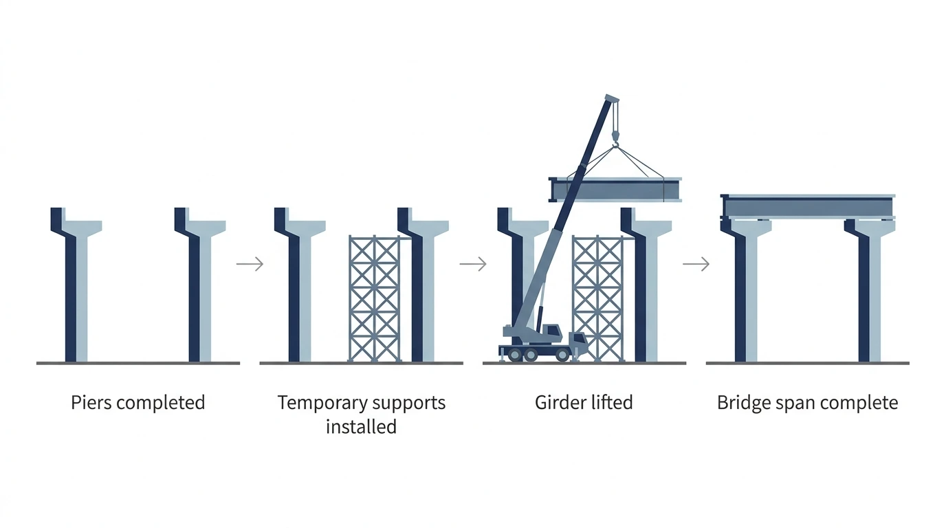
Figure 1. Four stages of girder bridge erection, from completed pier to removal of temporary supports.
What Is 4D Bridge Construction Simulation, and How Does It Differ from 3D?
4D bridge construction simulation combines a 3D bridge model with the dimension of time, namely the construction schedule, so that each structural element appears, moves or is removed on its planned date. A 3D model answers questions about shape and position, while a 4D simulation answers questions about order and timing. The two complement each other and are typically built on a Building Information Modeling (BIM) approach. The U.S. Federal Highway Administration (FHWA) describes BIM as a set of tools and methods for building a three-dimensional digital representation of a project that gathers data from multiple sources.
The 3D model contains the geometry of piers, pier heads, girders, deck slabs and bearings, as well as temporary elements such as falsework and formwork. Once the model is linked to each activity in the schedule, simulation software can play the sequence like a film, with the ability to pause, rewind and compare two method scenarios side by side. The practical differences are summarized below.
| Aspect | Conventional 2D drawings | 3D model | 4D simulation |
|---|---|---|---|
| Question answered | What are the dimensions and where is it? | What is the shape and how do elements relate? | When, in what order and with which equipment is each element installed? |
| Clash detection | Manual, dependent on the reader's diligence | Automated for the final condition | Includes clashes at intermediate stages and with working equipment |
| Communication to management | Requires long technical explanation | Visual but static | Visual and sequential, understood across functions |
| Evaluation of alternative methods | Difficult and slow | Limited to geometry | Side-by-side scenario comparison |
What Can Be Tested in a Bridge Erection Sequence Simulation
A good simulation tests the items that are most expensive to get wrong on site: space, equipment, sequence and safety. The four groups of checks below tend to add the most value on bridge projects.
Geometry and clashes between stages
The most dangerous clash is the one discovered when a segment is already suspended in the air. Simulation checks whether a segment can reach its position without touching falsework, protruding reinforcement or elements already installed. The check also covers intermediate stages, for example when stay cables are not yet tensioned or temporary supports have not yet been released.
Equipment capacity and working space
Crane selection, boom reach, bearing points and swing radius can be visualized together with site conditions. The team can see whether two machines can work at the same time without interfering, and whether access routes and segment storage areas are large enough. For work over water or over active roads, simulation helps define the safest working windows.
Temporary works and safety
Temporary works such as falsework, supports and bracing are a frequent source of accidents because they receive little attention in drawings. By showing when temporary elements are installed and removed, the safety team can identify hazard zones, set exclusion areas and prepare work procedures that follow the real sequence. It should be stated clearly that a visual simulation does not replace construction-stage structural analysis by a qualified engineer. The simulation shows a sequence that has been analyzed; it does not verify its strength.
Logistics and schedule quality
When each segment is linked to production, delivery and installation dates, hidden dependencies become visible. Examples include segments arriving before the storage area is ready, or installation waiting on concrete curing that has not been scheduled. Simulation helps test whether the master schedule can truly be executed, not merely whether it is consistent on paper.

Figure 2. 4D simulation used in project decision meetings and briefings, not only in presentations.
Business Impact: Risk, Cost and Schedule
The main business impact of bridge construction simulation is that problems are discovered at the desk, where they are cheap to fix, rather than on site. Every issue found before heavy equipment is mobilized represents one avoided rework item, one avoided delay or one avoided incident. A case study of a 4D bridge information model on a concrete flyover project, published in the proceedings of the International Group for Lean Construction (IGLC), reported better visualization, coordination and communication, and concluded that the approach can help prevent problems, rework, and cost and schedule overruns. The result of a single case study cannot be generalized, but it points in the same direction as the qualitative comparison below.
| Decision dimension | Without simulation | With 3D/4D simulation |
|---|---|---|
| Technical risk | Clashes and space shortages surface during execution | Most are detected and resolved during planning |
| Cost | Exposed to rework, equipment standby and sudden method changes | Equipment and labor needs are better defined; changes are made on the model |
| Schedule | Dependencies between stages are hidden in a bar chart | Dependencies are visible and the critical path can be re-tested |
| Safety | Procedures are drafted from the final-condition drawings | Procedures are drafted from the real sequence, including temporary stages |
| Stakeholder communication | Relies on verbal explanation and technical documents | One shared visual used by owner, consultant and contractor |
The size of any saving depends heavily on bridge complexity, data maturity and the quality of the simulation work. Organizations should therefore define their own indicators from the outset, for example the number of clashes found before construction, the number of method revisions needed on site, and the gap between planned and actual schedule. Indicators measured consistently become the basis for deciding whether to extend simulation to the next project.
A Decision Framework for Executives: When Is Simulation Worthwhile?
3D/4D simulation is most worthwhile when execution complexity is high and the cost of failure is large. Not every bridge requires the same depth of simulation. The five questions below can serve as an initial screening framework.
- Does the construction method involve interdependent stages, such as balanced cantilever, incremental launching or lifting heavy segments with several machines?
- Is working space constrained by a river, active roads, railway lines, utilities or a dense urban area?
- Are many parties involved, such as the owner, design consultant, main contractor and specialist subcontractors, who must agree on one work sequence?
- Is schedule tolerance narrow, for instance because traffic closures are only permitted at certain times?
- Does the project require the method to be demonstrated to the owner or a regulator before work begins?
If three or more questions are answered yes, 4D simulation should be built into the project plan from the method-planning phase rather than added after problems appear. If only one or two apply, a 3D model with clash checking and a limited simulation of the most critical stage is often sufficient.
Implementation Steps for Bridge Construction Simulation
Successful adoption starts from a clear decision objective, not from buying software. The simulation is built to answer a specific question, for example which method is safer or which schedule is more realistic. The staged approach below helps control cost and focus.
| Stage | Main activities | Output | Responsible |
|---|---|---|---|
| 1. Define objectives | Determine the decisions the simulation should support and the level of model detail | Scope and success criteria | Project director |
| 2. 3D modeling | Build the permanent structure and temporary works from drawings and site data | Coordinated 3D model | BIM and engineering team |
| 3. Schedule preparation | Break the schedule down to the erection-sequence level and link it to model elements | Model-linked schedule | Planning engineer |
| 4. Simulation and scenario testing | Run the sequence, check clashes and compare alternative methods | List of findings and recommendations | Construction methods team |
| 5. Cross-party review | Present the simulation to owner, consultant and subcontractors and agree the sequence | Approved erection sequence | Project manager |
| 6. Use on site | Use the simulation for daily briefings and update the model as work progresses | Up-to-date model | Site and BIM teams |
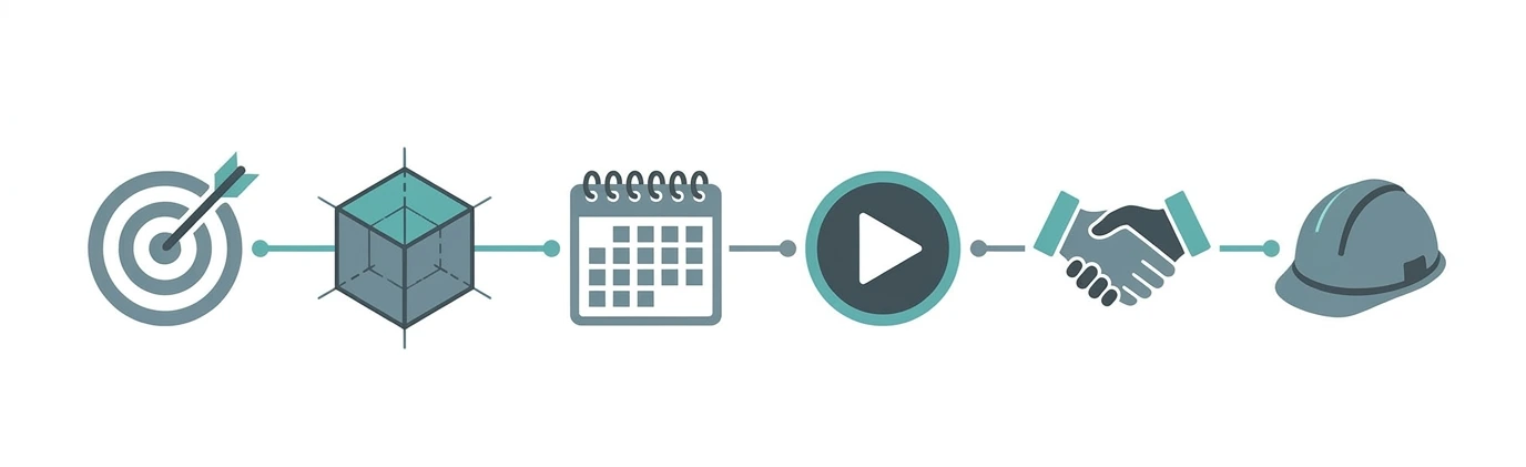
Figure 3. Six stages for adopting bridge construction simulation, from setting objectives to use on site.
Governance and Limitations to Anticipate
A simulation is only as good as the data fed into it, so data governance is a condition of success. A model that is not kept current will quickly lose the trust of the team. Several matters should be decided at the outset.
- Model ownership and versioning. Define who is authorized to update the model, how changes are recorded and where the latest version is stored. BIM-based information management practices, such as the ISO 19650 framework, can serve as a reference for a common data environment.
- Proportionate level of detail. An overly detailed model slows work without improving the quality of decisions. Detail should be limited to elements that affect sequence, space and safety.
- Separation of analysis and visualization. Construction-stage structural analysis remains the responsibility of a qualified engineer. The simulation presents the result and tests space and sequence.
- Competence and working habits. Simulation creates value when its output is used in decision meetings and site briefings. If it remains a presentation file, the investment does not pay back.
- Quality of the source schedule. A schedule that does not detail the erection sequence cannot be simulated meaningfully, so refining the schedule is often the most decisive early task.
Conclusion
A hard-to-visualize erection sequence no longer has to be a barrier once bridge construction can be simulated in 3D and 4D. 4D bridge construction simulation turns an abstract work sequence into a picture that directors, technical teams, owners and subcontractors can see, test and agree on before heavy equipment reaches the site. Its strategic value lies in faster decisions, better-controlled risk and a schedule that can be defended with evidence.
The next step for management is simple: select one bridge project with genuine execution complexity, define three success indicators, and run a simulation on the most critical stage. The results of that pilot will provide an objective basis for deciding whether to extend the approach across the wider project portfolio.
To discuss 3D/4D bridge construction simulation for your project, contact the Fujicon Japan team:
- WhatsApp: +6281122275222
- Website: www.fujicon-japan.com
References
- Federal Highway Administration (FHWA). Building Information Modeling (BIM) for Bridges and Structures
- Application of 4D Bridge Information Model as a Lean Tool for Bridge Infrastructure Projects: A Case Study. IGLC
- ISO 19650-1:2018, Organization and digitization of information about buildings and civil engineering works, including BIM (standard listing, AFNOR)